
Engineering prototype · dissected
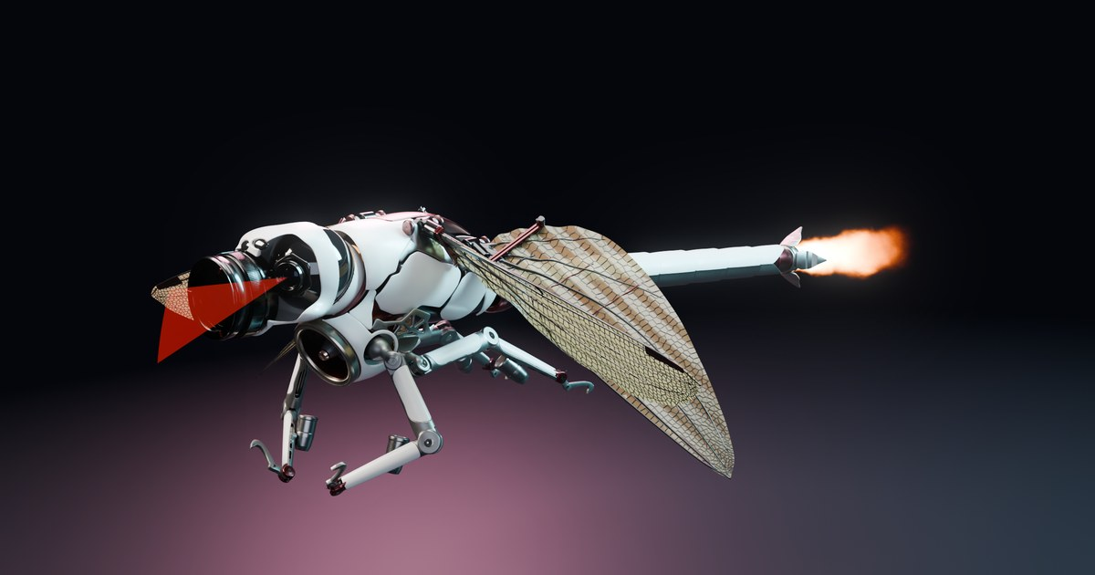
Dragon Flycore: a robot dragonfly prototype, dissected, simulated and built
Every motor, gear, fan and sensor of a four-wing robot dragonfly, explained in 3D. Then the two guides that follow: how to build a physics simulator for it in Unreal Engine 5 or Unity, and how to build a real, flying prototype 45 cm long.
The short answer
Dragon Flycore is an engineering concept of a security robot dragonfly: four flapping wings for lift, an electric ducted fan in the chest that pushes air out of the tail, four small thrusters on the legs, folding wings and two scanning cameras. It was built part by part in Blender at real scale, with working gears and linkages and a mass for every part.
- Simulate it in Unreal Engine 5 (Chaos physics, async physics tick) or Unity 6 (PhysX, fixed steps of 1 to 2 ms). Neither engine knows how a flapping wing makes lift, so you add a blade-element aerodynamics module: the code and a tested Python reference are below.
- Build a robot dragonfly prototype at 0.45 m long, 0.70 m span and about 300 g, close to the size of Festo’s flying BionicOpter (44 cm, 63 cm span, 175 g) [1]. The full 0.81 m, 1.73 kg concept loads each square metre of wing about six times harder than P1 does, too much for flapping wings.
- The turbines are electric ducted fans. The fire in the 3D model and the videos is a visualization of thrust: an electric fan blows plain, invisible air.
Dissect it in 3D
Press Play to load the robot (5.3 MB). Pick a part in the list or tap the model: the camera flies to it and a card explains what it does, with the part you would use on a real prototype. X-ray fades the shells so you can watch the gears and cranks turn, Explode pulls the subsystems apart, and the clip buttons switch between the seven flight modes.

Dissect Dragon Flycore in 3D
Seven flight clips with Blender-rendered thruster fire, 14 parts explained, X-ray and exploded views.
Keys: 1 to 7 switch clips, Space pauses, X toggles X-ray, Esc closes the card. The wing beats play 16 times slower than real time so that a 24 Hz beat stays readable.
Concept and prototype: two machines
The Blender model is a concept: it answers “could every part fit and move?”. Every joint sits on its pin, the crank-rocker linkages are solved exactly (the rod length never changes by more than 0.00007 mm over a beat), and the mass of each of its more than 300 parts comes from its volume and material. The robot dragonfly prototype, P1, answers a different question: what can you build and fly with parts you can buy and print today?
| Dragon Flycore CAD v2 | P1 prototype (proposed) | |
|---|---|---|
| Length × span | 0.81 × 0.68 m | 0.45 × 0.70 m |
| Mass | 1.73 kg (CAD, every part) | 300 g (budget below) |
| Wing area (4 wings) | 800 cm² | 825 cm² |
| Wing loading | 212 N/m² | 36 N/m² |
| Flapping | 24–28 Hz, 100° stroke | hover ≈ 11.1 Hz, up to 16 Hz, 90° stroke |
| Wing drive | 2 BLDC motors, 8.44:1 gears, crank-rockers | 2 outrunners of the 1404 class, 16:1 gears, crank-rockers |
| “Turbines” | 50 mm chest EDF (6.3 N) + 4 × 15 mm leg EDFs | 30 mm EDF (≈ 1 N) + optional micro rotors |
| Structure | Ti-6Al-4V, S2-glass skins, carbon | SLS/MJF nylon shells, carbon tubes, PET film |
| Battery | 39 Wh pouch packs | 2S LiPo, 850 to 1300 mAh |
Exploded view: the subsystems
Pulled apart along their mounting directions, the 15 subsystems show the logic of the layout: sensors forward, the heavy drive and battery in the thorax between the wing roots (the centre of gravity sits between the fore and hind wing roots), the long abdomen as a duct and a lever for the tail jet.


How it flies: the logic
The rule behind the whole design: the wings lift, the fan pushes. All thrusters together give 8.6 N, half the 17 N weight, so every mode with the wings folded is a short manoeuvre that lives on speed or height the robot already has. These are first-order hand calculations from the CAD files, not flight tests.
| Mode | What does the work | First-order numbers (CAD) |
|---|---|---|
| Cruise | wings lift, chest fan pushes | 29.5 m/s (106 km/h), about 240 W, 9.7 min on 39 Wh |
| Fold + tail-jet dash | folded slender body + tail jet | a powered glide 8° down at 29 m/s; trades height for speed |
| 45° climb | chest fan + leg pods | a zoom climb of about 2.5 s and 37 m, paid for by the dash speed |
| Vertical boost | leg pods down | pods give 2.4 N = 14 % of the weight: they brake a drop, they cannot hover |
| Banked turn | differential feather + outer pods + paddles | 26° bank at 11 m/s, radius 25 m |
| Perched | claws on a ledge or cable | 9 W for cameras and radio: 4.3 hours |
What real dragonflies teach the design
Dragonflies drive each of their four wings with their own muscles, beat the fore and hind pairs out of phase, and hover on an inclined stroke plane where drag, not lift, carries about three quarters of the weight [2]. The pterostigma, the dark cell near each wing tip, is a small weight that sets how the wing pitches [3]. The robot copies all three ideas: two drive trains, a 90° phase between the pairs, and a tungsten-filled pterostigma.


Every motor and turbine, dissected
The concept carries dozens of actuators, from the wing drives to the iris blades of its zoom lens. The table takes the ones that matter for flight and pairs each with the real part class that does the same job on P1. Masses are planning estimates for P1; weigh your parts.
| Actuator | Job | In the CAD | On P1 (real parts) | P1 mass |
|---|---|---|---|---|
| Fore wing drive | flaps the fore wings | BLDC → 12T → 38/12T → 2 × 32T (8.44:1) → crank-rocker | 1404-class outrunner, 2 spur stages ≈ 16:1, crank-rocker | ≈ 18 g with gears |
| Hind wing drive | flaps the hind wings, 90° behind | the same | the same, its own motor so the phase can change | ≈ 18 g |
| Feather servos × 4 | wing pitch: roll and paddling | servo bias on a passive flip | 2–4 g micro servos | 12 g |
| Fold actuators × 4 | fold the wings back | worm gearmotor on a 2.6 mm pin | phase 2: micro worm gearmotor | ≈ 6 g |
| Chest EDF | forward thrust | 50 mm EDF, 7 blades, 11 vanes, 6.3 N | 30 mm EDF, ≈ 1 N at ≈ 100 W | 12 g + ESC |
| Tail paddles × 4 | turn the jet | linear servos at the nozzle exit | 2 linear servos (yaw, pitch) | ≈ 3.5 g |
| Leg pods × 4 | brake, jump, roll in turns | 15 mm EDF, 0.6 N each, tilt servo | optional fixed micro rotors | ≈ 20 g |
| Hip drives × 4 | pose the legs | 3 motors per leg, push-rod knee | passive legs + 1 tendon servo | ≈ 3 g |
| Risley scanners × 2 | sweep a laser line | rotating 2° glass wedge | leave out; use a ToF chip | — |
1. The wing drive: motor, gears, crank-rocker
A brushless motor turns fast and weakly; a wing must swing slowly and strongly. The gearbox trades speed for torque (8.44:1 in the CAD, about 16:1 on P1), and the crank-rocker turns rotation into a back-and-forth swing. The two output gears mesh with each other, so they turn in opposite directions and the left and right wings are always exact mirror images: the stroke cannot roll the robot by accident. Roll comes from the feather servos instead.


Wing inertia is the hidden load. Each beat the wings stop and reverse, and the gears must carry that peak torque: about 0.8 N·m per wing pair on P1 at hover frequency and 1.7 N·m at 16 Hz. That energy goes out and comes back each stroke, so the motor mostly pays for the air. Insects store it in an elastic protein (resilin) at the hinge; a spring at the wing root does the same for a robot and lowers the gear load.
2. Feather, fold and paddle servos
Small servos change the shape of the stroke rather than drive it. Twisting the left wing up and the right wing down rolls the robot like ailerons; twisting both more on the downstroke than the upstroke makes a net vertical force, the paddling that lets a level body hover. The fold actuator uses a worm stage because a worm cannot be back-driven: it holds the wing open or folded with the power off.


The fold borrows from Grumman’s Sto-Wing [4]: any change of orientation is a single rotation about one axis, so one fixed, skewed pin can fold a wing back along the body. Dragon Flycore’s pins were solved to stand vertical at flap 0, with 14.8 mm of clearance along the whole swing.
3. The “turbines”: electric ducted fans and the fire
The chest fan is an electric ducted fan (EDF): a brushless motor spins a many-bladed rotor inside a duct, and fixed stator vanes behind it straighten the swirl into thrust. In the CAD the 7 rotor blades and 11 vanes are co-prime numbers, so no blade passes all the vanes at once and the tone stays lower. Its air splits like a turbofan’s: 47 g/s down the abdomen to the 22 mm tail nozzle (4.7 N), 35 g/s over the batteries and out through the slits under the first segment (1.6 N).


Why not a real turbine with real fire? The smallest model turbojets give about 24 N for roughly 350 g [5]: more than P1 weighs, with a hot exhaust, kerosene and a fire risk next to a film wing. A 30 mm EDF of about 12 g gives roughly 1 N at about 100 W (seller data) [6], which is 0.36 times P1’s weight, almost the same ratio as the concept’s 0.37. So the fire you see is drawn on purpose, shaped after real afterburner exhaust with its shock diamonds.


Four paddles at the nozzle exit turn the jet, as on NASA’s X-31 [7]: about 0.3° of jet per degree of paddle. Yaw in the turns, pitch in the climb.


4. Sensors, scanners and the brain
The wide camera sits on a 2-axis gimbal. In front of each lens a 2° glass wedge spins: two rotating wedges, or Risley prisms, steer a beam around a cone, the way some lidars scan. Each scanner projects a 650 nm laser line. For P1, a multizone time-of-flight chip of about a gram replaces the scanning optics, and a small camera module replaces the zoom lens.


Part A · Build a simulator in Unreal Engine 5 or Unity
A game engine gives you rigid bodies, joints, contacts and beautiful rendering. It does not know how a flapping wing makes lift: no engine does. So a flapping-robot simulator is an engine plus four modules you write: aerodynamics, actuators, power and sensors, with a flight controller in the loop.
Which software to use
| Layer | Unreal Engine 5 | Unity |
|---|---|---|
| Engine | Unreal Engine 5.4 or later | Unity 6 (LTS) |
| Rigid-body physics | Chaos, with Tick Physics Async at 1–2 ms | PhysX: Rigidbody, or ArticulationBody for the legs; Fixed Timestep 0.001–0.002 s |
| Import the robot | GLB/FBX for the look; joints and masses from the URDF | URDF Importer (ArticulationBody) [8], GLB via glTFast |
| Flapping aerodynamics | your C++: FlycoreAero below |
your C#: FlycoreWingAero below |
| Sensors and maps | Colosseum, the UE5 port of AirSim [9], or Project AirSim [10]; Cesium for real terrain | camera and depth components; ROS-TCP-Connector for ROS 2 |
| Flight controller in the loop | your controller in C, or ArduPilot SITL over its JSON interface [11] | the same |
| Learning a controller | Learning Agents plugin [12] | ML-Agents 4.x [13] |
| Fire and look | Niagara (flipbook or GPU fluid) | VFX Graph (flipbook sprites) |
Pick Unreal Engine 5 if the simulator is also a showcase (cinematic look, large outdoor maps, Niagara fire) or you want the AirSim heritage for sensors. Pick Unity for fast iteration in C#, the URDF importer and ML-Agents for training controllers. The physics that matters, the wing model, is the same in both.
The physics: a quasi-steady blade-element model
Cut each wing into 12 to 20 strips from root to tip. For every strip, every physics step:
- Find how fast the strip moves through the air: flapping speed + the body’s velocity + its rotation, minus the downwash the wings push down.
- Find the angle of attack α between that airflow and the wing’s chord.
- Look up lift and drag coefficients measured on flapping wings [16]: CL = 0.225 + 1.58 sin(2.13α − 7.2°), CD = 1.92 − 1.55 cos(2.04α − 9.82°).
- Force = ½ ρ U² × chord × strip width × C. Lift is normal to the airflow, drag is along it. Apply it at the strip’s quarter-chord point.
Two corrections make the numbers honest. The fruit-fly coefficients come from a tiny wing at a Reynolds number near 100; P1’s wing runs near 54,150, with a flexible film and a hind wing in the fore wing’s wake, and quasi-steady models are known to underestimate drag [17]. So the reference multiplies lift by 0.7 and drag by 1.25. It also adds the rotational lift of the flip at each stroke reversal [18] and a uniform downwash from momentum theory.
Time step: a 16 Hz beat needs at least 40 samples per stroke for stable forces, so run the aerodynamics at 1 to 2 kHz, on the physics thread. For a game that only needs the look, average the forces over one beat and apply them at 60 to 120 Hz.
Posture matters: with the flap hinges along the body, as on Dragon Flycore, symmetric feathering pushes along the body axis. Level, that is thrust; pitched nose-up, it is lift. The engine code below computes forces from the strip’s real motion and the wing’s real orientation, so it gets this right for any posture: it reproduces the reference exactly (4.283 N at 12 Hz) when the stroke plane is horizontal, and gives the forward thrust when the body is level.
Unity 6: FlycoreWingAero.cs
- Import the robot. Put one Rigidbody on the body with the CAD mass and centre of mass (or import the URDF as ArticulationBodies).
- Set Project Settings › Time › Fixed Timestep to 0.001–0.002 s, or switch to
SimulationMode.Scriptand callPhysics.Simulatein fixed sub-steps [19]. - Drive the wing transforms from the animation clips or a crank script, then add this component to each of the four wings and set its span and chord axes.
- Add an EDF thruster (thrust ∝ rpm² with a first-order lag of about 50 ms), servo rate limits and a battery model with voltage sag.
// FlycoreWingAero.cs - quasi-steady blade-element aerodynamics for one flapping wing (Unity 6, built-in PhysX).
// robotanimator.org, Dragon Flycore prototype guide. Port of flycore_quasi_steady.py: compare its printed numbers with your scene.
// Put it on the wing's Transform (animated by clips, a crank script or joints). It reads where each wing strip really moves,
// so it works in hover and in forward flight, and pushes the robot's Rigidbody with AddForceAtPosition.
// Left out on purpose (add them once the basics match your bench data): the rotational-lift term of the Python model, added mass, wing-wing interaction.
// Run physics fast enough for the beat: Project Settings > Time > Fixed Timestep = 0.001 to 0.002 s (500 to 1000 Hz).
using UnityEngine;

public class FlycoreWingAero : MonoBehaviour
{
    [Header("Wing geometry (metres, in this Transform's local axes)")]
    public Rigidbody body;                         // the robot's main Rigidbody
    public Vector3 spanAxis = Vector3.right;        // local direction from wing root to tip
    public Vector3 chordAxis = Vector3.forward;     // local direction from trailing edge to leading edge
    public float rootOffset = 0.035f;               // hinge to wing root
    public float length = 0.30f;                    // root to tip
    public float chordMax = 0.08f;                  // semi-elliptic planform
    [Range(4, 40)] public int strips = 16;

    [Header("Air and safety factors")]
    public float airDensity = 1.20f;                // kg/m3
    public float kLift = 0.7f, kDrag = 1.25f;       // same derating as the Python reference
    public Vector3 downwash = Vector3.zero;         // optional uniform induced velocity (world, m/s), e.g. from momentum theory

    [Header("Read-only")]
    public Vector3 lastForce;                       // world N, this step

    Vector3[] prev;
    bool primed;

    static float CL(float aDeg) => 0.225f + 1.58f * Mathf.Sin((2.13f * aDeg - 7.2f) * Mathf.Deg2Rad);   // Dickinson et al. 1999
    static float CD(float aDeg) => 1.92f - 1.55f * Mathf.Cos((2.04f * aDeg - 9.82f) * Mathf.Deg2Rad);

    float Chord(float rn) => chordMax * Mathf.Sqrt(Mathf.Max(0f, 1f - (2f * rn - 1f) * (2f * rn - 1f)));

    Vector3 StripPoint(int i, out float dr, out float c)
    {
        dr = length / strips;
        float rn = (i + 0.5f) / strips;
        c = Chord(rn);
        // the span axis should run along the wing's quarter-chord line, where the force acts
        return transform.TransformPoint(spanAxis.normalized * (rootOffset + rn * length));
    }

    void FixedUpdate()
    {
        if (body == null) return;
        float dt = Time.fixedDeltaTime;
        if (prev == null || prev.Length != strips) { prev = new Vector3[strips]; primed = false; }
        Vector3 n = transform.TransformDirection(Vector3.Cross(chordAxis, spanAxis).normalized);   // wing normal
        Vector3 s = transform.TransformDirection(spanAxis.normalized);
        Vector3 ch = transform.TransformDirection(chordAxis.normalized);
        Vector3 total = Vector3.zero;
        for (int i = 0; i < strips; i++)
        {
            Vector3 p = StripPoint(i, out float dr, out float c);
            Vector3 v = primed ? (p - prev[i]) / dt : body.GetPointVelocity(p);   // world velocity of the strip (flapping + body motion)
            prev[i] = p;
            Vector3 u = downwash - v;                                           // air velocity seen by the strip
            u -= Vector3.Dot(u, s) * s;                                         // spanwise flow carries no blade-element force
            float speed = u.magnitude;
            if (speed < 1e-4f) continue;
            Vector3 uh = u / speed;
            float alpha = Mathf.Acos(Mathf.Clamp01(Mathf.Abs(Vector3.Dot(uh, ch)))) * Mathf.Rad2Deg; // 0..90 deg
            Vector3 nn = Mathf.Sign(Vector3.Dot(u, n)) * n;                    // the air pushes the plate along its normal component
            Vector3 eL = (nn - Vector3.Dot(nn, uh) * uh).normalized;           // lift: normal to the flow, in the flow-normal plane
            float q = 0.5f * airDensity * speed * speed * c * dr;
            Vector3 f = kLift * q * CL(alpha) * eL + kDrag * q * CD(alpha) * uh; // drag acts along the air velocity
            body.AddForceAtPosition(f, p, ForceMode.Force);
            total += f;
        }
        primed = true;
        lastForce = total;
    }
}
Unreal Engine 5: FlycoreAero on the async physics tick
- Enable Project Settings › Physics › Tick Physics Async and set the async fixed time step to 1–2 ms [20].
- Make a Pawn with one simulating body (CAD mass, centre of mass at the actor origin) and the skeletal mesh for the look.
- Compute the wing loads on the physics thread every step and add them as force and torque. Animation follows the same phase for the visuals.
- Remember Unreal’s units: 1 N is 100 kg·cm/s² and 1 N·m is 10 000 kg·cm²/s².
// FlycoreAero.h - quasi-steady blade-element loads of one flapping wing, engine-independent (metres, newtons, radians).
// robotanimator.org, Dragon Flycore prototype guide. Same math as FlycoreWingAero.cs and general_check.py, which reproduces
// flycore_quasi_steady.py exactly (4.283 N at 12 Hz for the P1 wings, horizontal stroke plane, no rotational term).
// Body frame = Unreal actor frame: X forward, Y right, Z up. The flap hinge runs along X; feather turns the wing about its span.
#pragma once
#include "CoreMinimal.h"

struct FFlycoreWing
{
    FVector HingeM = FVector::ZeroVector;  // hinge point in the body frame, metres
    float Side = 1.f;                      // +1 right wing, -1 left wing
    float RootOffsetM = 0.035f, LengthM = 0.30f, ChordMaxM = 0.08f;
    float StrokeDeg = 90.f;                // peak to peak
    float AlphaMidDeg = 40.f;              // mid-stroke angle of attack
    float FlipFraction = 0.22f;            // share of the period spent flipping at each reversal
    float PhaseRad = 0.f;                  // hind wings: the fore pair leads by 90 deg on Dragon Flycore
    float TwistBiasDeg = 0.f;              // control input: + pitches the leading edge up on both strokes (asymmetry = paddling)
};

namespace FlycoreAero
{
    constexpr float KLift = 0.7f, KDrag = 1.25f, Rho = 1.2f;
    inline float CL(float A) { return 0.225f + 1.58f * FMath::Sin(FMath::DegreesToRadians(2.13f * A - 7.2f)); }
    inline float CD(float A) { return 1.92f - 1.55f * FMath::Cos(FMath::DegreesToRadians(2.04f * A - 9.82f)); }

    // Loads of one wing at time TimeS, in the body frame: force (N) and moment about the body origin (N m).
    // BodyVelMS and BodyOmega (rad/s) are the body's velocity and angular velocity, also in the body frame.
    // DownwashMS is an optional uniform induced velocity (body frame, m/s): air moving towards -Z when hovering.
    void WingLoads(const FFlycoreWing& W, float FlapHz, float TimeS, const FVector& BodyVelMS, const FVector& BodyOmega,
                   const FVector& DownwashMS, FVector& OutForceN, FVector& OutMomentNm, int32 Strips = 16);
}// FlycoreAero.cpp - see FlycoreAero.h. robotanimator.org
#include "FlycoreAero.h"
namespace
{
// angle of attack (deg) over one period: AlphaMid in mid-stroke, a smooth flip through 90 deg at each reversal (tn = 0 and 0.5)
float PitchLaw(float Tn, float AlphaMid, float Flip)
{
float Best = 2.f;
for (float Tr : {0.f, 0.5f, 1.f}) { const float D = Tn - Tr; if (FMath::Abs(D) < FMath::Abs(Best)) Best = D; }
const float H = Flip * 0.5f;
if (FMath::Abs(Best) >= H) return AlphaMid;
const float X = Best / H; // -1 .. 1 through the flip
const float S = 0.5f * (1.f - FMath::Cos(PI * (X + 1.f) * 0.5f));
return AlphaMid + (90.f - AlphaMid) * (1.f - FMath::Abs(2.f * S - 1.f));
}
float ChordAt(float Rn, float CMax) { const float K = 2.f * Rn - 1.f; return CMax * FMath::Sqrt(FMath::Max(0.f, 1.f - K * K)); }
}
void FlycoreAero::WingLoads(const FFlycoreWing& W, float FlapHz, float TimeS, const FVector& BodyVelMS, const FVector& BodyOmega,
const FVector& DownwashMS, FVector& OutForceN, FVector& OutMomentNm, int32 Strips)
{
OutForceN = FVector::ZeroVector; OutMomentNm = FVector::ZeroVector;
const float Omega = 2.f * PI * FlapHz;
const float Amp = FMath::DegreesToRadians(W.StrokeDeg) * 0.5f;
const float Ph = Omega * TimeS + W.PhaseRad;
const float Phi = Amp * FMath::Cos(Ph);
const float DPhi = -Amp * Omega * FMath::Sin(Ph);
const float Tn = FMath::Frac(Ph / (2.f * PI));
const float AGeo = PitchLaw(Tn, W.AlphaMidDeg, W.FlipFraction);
// feather: the leading edge points into the motion (sign of DPhi); TwistBias adds the same pitch-up on both strokes
const float Theta = FMath::DegreesToRadians(FMath::Sign(DPhi) * (90.f - AGeo) + W.TwistBiasDeg);
const FVector Span(0.f, W.Side * FMath::Cos(Phi), FMath::Sin(Phi)); // root -> tip
const FVector N0(0.f, -W.Side * FMath::Sin(Phi), FMath::Cos(Phi)); // zero-feather normal = stroke tangent
const FVector Chord = FMath::Cos(Theta) * FVector::ForwardVector + FMath::Sin(Theta) * N0; // towards the leading edge
const FVector Normal = -FMath::Sin(Theta) * FVector::ForwardVector + FMath::Cos(Theta) * N0;
const float Dr = W.LengthM / Strips;
for (int32 i = 0; i < Strips; ++i)
{
const float Rn = (i + 0.5f) / Strips;
const float R = W.RootOffsetM + Rn * W.LengthM;
const float C = ChordAt(Rn, W.ChordMaxM);
const FVector P = W.HingeM + Span * R; // quarter-chord point, body frame
const FVector V = BodyVelMS + FVector::CrossProduct(BodyOmega, P) + N0 * (R * DPhi);
FVector U = DownwashMS - V; // air velocity seen by the strip
U -= FVector::DotProduct(U, Span) * Span;
const float Speed = U.Size();
if (Speed < 1e-4f) continue;
const FVector Uh = U / Speed;
const float Alpha = FMath::RadiansToDegrees(FMath::Acos(FMath::Min(1.f, FMath::Abs(FVector::DotProduct(Uh, Chord)))));
const FVector Nn = FMath::Sign(FVector::DotProduct(U, Normal)) * Normal;
const FVector EL = (Nn - FVector::DotProduct(Nn, Uh) * Uh).GetSafeNormal();
const float Q = 0.5f * Rho * Speed * Speed * C * Dr;
const FVector F = KLift * Q * CL(Alpha) * EL + KDrag * Q * CD(Alpha) * Uh;
OutForceN += F;
OutMomentNm += FVector::CrossProduct(P, F);
}
}/* ---------------------------------------------------------------- how a pawn uses it (a sketch; check the Chaos names in your engine version)
Project Settings > Physics > Framerate: enable "Tick Physics Async" and set the async fixed time step to 0.001 to 0.002 s.
AFlycorePawn::AFlycorePawn() { bAsyncPhysicsTickEnabled = true; }
void AFlycorePawn::AsyncPhysicsTickActor(float DeltaTime, float SimTime)
{
Super::AsyncPhysicsTickActor(DeltaTime, SimTime);
FBodyInstance* BI = BodyMesh->GetBodyInstance();
Chaos::FRigidBodyHandle_Internal* H = BI && BI->GetPhysicsActorHandle() ? BI->GetPhysicsActorHandle()->GetPhysicsThreadAPI() : nullptr;
if (!H) return;
const FTransform Pose(H->R(), H->X()); // world, centimetres
const FVector VelB = Pose.InverseTransformVectorNoScale(H->V()) / 100.f; // body frame, m/s
const FVector OmB = Pose.InverseTransformVectorNoScale(H->W()); // rad/s
FVector FB = FVector::ZeroVector, MB = FVector::ZeroVector;
for (const FFlycoreWing& W : Wings) // 4 wings, read-only copies made on the game thread
{
FVector F, M; FlycoreAero::WingLoads(W, FlapHz, SimTime, VelB, OmB, FVector(0, 0, -DownwashMS), F, M);
FB += F; MB += M;
}
// Unreal units: 1 N = 100 kg cm/s^2, 1 N m = 10000 kg cm^2/s^2. Moments here are about the body origin: put it at the centre of mass.
H->AddForce(Pose.TransformVectorNoScale(FB) * 100.f, false);
H->AddTorque(Pose.TransformVectorNoScale(MB) * 10000.f, false);
}
Only touch physics-thread data inside AsyncPhysicsTickActor; pass control inputs (FlapHz, TwistBiasDeg) in from the game thread
through atomics or the async input objects, never by reading components there. */Flight control and learning
Write the controller in plain C so the same code runs in the simulator and on the robot’s microcontroller (software in the loop). If you prefer a full autopilot, ArduPilot’s SITL accepts physics from any program over a simple UDP JSON link [11]: your engine sends the robot state and receives servo outputs. For learned control, train in the engine with domain randomization (mass, centre of mass, motor delay, gusts): a drone controller trained this way in simulation has beaten human champions [21].


Validate it
A simulator is only as good as the numbers you feed it. Mount one wing pair on a load cell, record the mean lift and the motor current from 8 to 16 Hz, and fit the two safety factors (0.7 and 1.25) to your data. Then film a tethered hover at high frame rate and compare the body motion with the simulation.
Part B · Build a real prototype: P1
A realistic size: 45 cm long, 70 cm span, 300 g
How big should a robot dragonfly prototype be? Real flapping robots that fly today sit between 30 and 65 cm of span and 30 and 180 g [22] [23] [1]. P1 sits at the top of that range, so there is room for a camera, a ducted fan and real perching legs, while staying a size you can build on a desk.


P1 by the numbers
| P1 (model) | |
|---|---|
| Wings | 4 × 300 mm long, 80 mm (fore) and 95 mm (hind) maximum chord, 825 cm² in all |
| Wing loading | 36 N/m² (the concept: 212) |
| Hover | 11.1 Hz at a 90° stroke; 12.7 Hz for 1.3 × the weight |
| Top beat | 16 Hz: 6.1 N of lift, 2.06 × the weight, wing tips at 26.5 m/s |
| Hover power | 48 W aerodynamic; ≈ 86 W from the battery (gears 85 %, crank 92 %, motor and ESC 75 %, + 4 W avionics) |
| Hover time | 3.5 min on 2S 850 mAh, 5.4 min on 2S 1300 mAh; forward flight costs less |
| Wing spar | 3.0/2.0 mm carbon tube, first bending mode ≈ 39 Hz, above twice the 16 Hz top beat |
| Gearing | motor near 15,000 rpm under load → 16 Hz needs 15.6:1: two spur stages of about 4:1 |
| Tail EDF | ≈ 1.06 N, 0.36 × the weight, ≈ 98 W |
Mass budget
| Item | Part class | Mass (g) |
|---|---|---|
| 4 wings | 3.0/2.0 mm carbon tube spar, 1 mm rods, 12–25 μm PET film | 14 |
| Wing roots, rockers, feather bearings | printed PA12-CF, 2 small bearings per wing | 10 |
| 2 flapping drives | 1404-class outrunner + 16:1 spur gearbox + crank-rocker | 37 |
| ESCs | 2 small brushless ESCs or one 4-in-1 board | 6 |
| 4 feather (twist) servos | 2–4 g micro servos | 12 |
| Tail EDF system | 30 mm EDF (12 g), ESC, printed duct and nozzle, 2 paddle servos | 27 |
| Leg thrusters (optional) | 4 micro ducted rotors + ESC | 20 |
| Flight controller + radio | Crazyflie Bolt class board | 5 |
| Camera + video link | micro camera module | 6 |
| Time-of-flight sensor | 8 × 8 zone ToF breakout | 2 |
| Battery | 2S 850 mAh LiPo | 48 |
| Fuselage | 0.8 mm SLS/MJF nylon shells, 6 mm carbon spine | 48 |
| Legs | printed PA12 + TPU knees, 1 tendon servo | 19 |
| Wiring, connectors, screws | 15 | |
| Total | + 31 g growth margin = 300 g design mass | 269 |
Motors and turbines for P1
- Flapping: two brushless outrunners of the 1404 class (about 9–10 g each), each with a two-stage spur gearbox (about 16:1, module 0.3–0.5) and a crank-rocker. One motor per wing pair keeps the fore-hind phase adjustable.
- Control: four 2–4 g servos twist the wings (roll, pitch, paddling), as on Festo’s BionicOpter, which flaps with one brushless motor and steers with servos on the wings.
- Thrust: one 30 mm EDF in the chest (≈ 1 N at ≈ 100 W on 2S, seller data [6]) with a printed S-duct to the tail and two paddle servos.
- Brain: a small flight controller with a 6-axis IMU. The Flapper Nimble+ flies on the open-source Crazyflie Bolt 1.1 (STM32F405) with a fork of the Crazyflie firmware [23]; it is a proven starting point for flapping-wing control.
- Sensors: a micro camera, an 8 × 8 zone time-of-flight sensor for landing and obstacles.
Materials and 3D printing
| Part | Material | Process and starting settings | Why |
|---|---|---|---|
| Thorax and head shells | PA12 or PA11 nylon | SLS or MJF, 0.8 mm walls | tough, light, no supports; dye black or prime and paint |
| Brackets, wing roots, rockers | PA12-CF or PA-CF filament | FDM, 0.4 mm nozzle, 0.12–0.16 mm layers, 4 walls, 40 % gyroid; dry the filament | stiff; print the wing-root lugs flat for strength |
| First test parts, jigs | PETG | FDM, 0.2 mm layers, 3 walls, 20 % gyroid | cheap; good for fit checks and the wing-laying jig |
| Knees, feet, bumpers | TPU 95A | FDM, slow (15–25 mm/s), direct drive | absorbs crashes |
| Small gears and bushings | tough engineering resin, or buy POM / brass | SLA or MSLA at 0.025–0.05 mm layers | buy the first stage: bought module 0.3–0.5 gears run quieter and longer |
| Wing spars and veins | pultruded carbon tube and rod | cut, glue with thin CA or epoxy | 3.0/2.0 mm tube main spar, 1 mm rods for the lattice |
| Wing membrane | PET (Mylar) film 12–25 μm; Kapton for looks | laminate on the frame with spray adhesive or transfer tape | film tension changes the twist: build both sides on the same jig |
| Spine and booms | carbon tube 6 mm | bought | the abdomen is a tube with printed ring fairings |


Making the wings
- Print a flat jig with grooves for the spar and the vein rods, mirrored for the left and right wings.
- Lay the 3.0/2.0 mm spar along the leading edge and the 1 mm rods along the vein lines; glue the joints with thin CA.
- Spray adhesive on the frame, lay the film over it under light, even tension, and trim with a hot knife 1 mm outside the frame.
- Add a few grams of tip weight (the pterostigma) to tune the passive pitch, then weigh each wing: pairs should match within 0.1 g.
- Check the first bending mode: tap the tip and film it, or excite it on a speaker. It must stay above twice the top beat frequency.
Build and test plan
| Phase | What you build | What you measure |
|---|---|---|
| 0 · Bench flapper | One drive train and one wing pair on a load cell | mean lift vs 8–16 Hz, motor current, wing tip deflection on high-speed video |
| 1 · Tethered hover | Full P1 on a light tether, wings only | attitude control with the twist servos, the hover frequency, the battery current |
| 2 · Free flight | Indoors, in a net | forward flight, turns, endurance |
| 3 · Tail EDF | Add the 30 mm EDF and the paddles | thrust, yaw and pitch authority, the dash |
| 4 · Legs and perching | Tendon claws and landing gear | perch on a rod, take off from it |
| 5 · Folding wings | Worm-geared fold actuators | fold and unfold at flap 0, the clearance |


Downloads
| File | Size | What it is |
|---|---|---|
| dragon-flycore.glb | 5.3 MB | the robot, 7 clips, Blender fire on the thrusters (meshopt compressed: open it in three.js, Blender 4.2+ or any glTF viewer that supports EXT_meshopt_compression) |
| flycore_quasi_steady.py | 10 KB | the flight model: run it to print every P1 number in this article |
| FlycoreWingAero.cs | 4 KB | Unity 6 component |
| FlycoreAero.h + .cpp | 7 KB | Unreal Engine 5 wing loads and pawn hook |
The 3D model and renders: robotanimator.org, CC BY 4.0. The code: free to use and change. More robots, rigs and prototypes are in the Robot Animator portfolio.
FAQ
Can a robot dragonfly really fly?
Yes. Festo’s BionicOpter (2013, 175 g, 63 cm span) and TU Delft’s DelFly Nimble (29 g, 33 cm span) both fly with flapping wings and no propellers for lift, and the Flapper Nimble+ is sold as a kit. Dragon Flycore’s full-size concept is too heavy for its wings; the 300 g P1 proposed here sits in the range those robots prove.
What size should a robot dragonfly prototype be?
About 45 cm long with a 70 cm span and 300 g. That keeps the wing loading near 36 N/m², so it hovers at about 11 Hz, with twice its weight in lift at 16 Hz, and leaves room for a camera, a ducted fan and perching legs.
Do the turbines burn fuel?
No. They are electric ducted fans: a motor spins a rotor inside a duct. The fire in the model and the videos is a visualization of thrust. The smallest real model turbojets weigh about 350 g, more than the whole prototype.
Unreal Engine 5 or Unity for a flapping-wing simulator?
Both work, because the part that matters, the wing aerodynamics, is your own code in either engine. Choose Unreal Engine 5 for visuals and large maps, Unity for fast C# iteration, the URDF importer and ML-Agents.
How long can the prototype fly?
The model gives about 3.5 minutes of hover on a 2S 850 mAh battery and about 5.4 minutes on 2S 1300 mAh. Forward flight costs less power, and perching with the motors off costs almost nothing.
Can I use the 3D model?
The GLB in the viewer is free to use with credit to robotanimator.org (CC BY 4.0), the same licence as the Dragon Flycore model on Sketchfab.
Sources and credits
- Festo (2013). BionicOpter: inspired by dragonfly flight. Technical data sheet. Link
- Wang, Z. J. (2004). The role of drag in insect hovering. J. Exp. Biol. 207: 4147-4155. Link
- Norberg, R. Å. (1972). The pterostigma of insect wings, an inertial regulator of wing pitch. J. Comp. Physiol. 81: 9-22. Link
- ASME. Historic Mechanical Engineering Landmark #238: the Grumman Wildcat “Sto-Wing” wing-folding mechanism (1941). Link
- JetCat P20-SX product page (about 24 N; retailers list about 350 g). Link
- Lindinger: PICHLER THRUST 30 mm impeller drive, KV 8000 (12 g, 108 g thrust, 98 W, 2S; seller data). Link
- NASA. X-31 enhanced fighter maneuverability: thrust-vectoring paddles (NTRS 19960029101). Link
- Unity Robotics Hub: URDF Importer and ROS-TCP-Connector. Link
- Colosseum: the community port of Microsoft AirSim to Unreal Engine 5. Link
- Project AirSim (IAMAI fork, MIT licence). Link
- ArduPilot developer docs: SITL with the JSON interface for external physics. Link
- Unreal Engine API: Learning Agents plugin. Link
- Unity ML-Agents Toolkit (package 4.x requires Unity 6). Link
- MuJoCo documentation: fluid forces (inertia and ellipsoid models). Link
- PX4 user guide: Gazebo simulation. Link
- Dickinson, M. H., Lehmann, F.-O. & Sane, S. P. (1999). Wing rotation and the aerodynamic basis of insect flight. Science 284: 1954-1960. Link
- Sane, S. P. & Dickinson, M. H. (2001). The control of flight force by a flapping wing: lift and drag production. J. Exp. Biol. 204: 2607-2626. Link
- Sane, S. P. & Dickinson, M. H. (2002). The aerodynamic effects of wing rotation and a revised quasi-steady model of flapping flight. J. Exp. Biol. 205: 1087-1096. Link
- Unity scripting reference: Physics.Simulate and SimulationMode.Script. Link
- Unreal Engine API: AsyncPhysicsTickComponent (async physics tick). Link
- Kaufmann, E., Bauersfeld, L., Loquercio, A., Müller, M., Koltun, V. & Scaramuzza, D. (2023). Champion-level drone racing using deep reinforcement learning. Nature 620: 982-987. Link
- Karásek, M., Muijres, F. T., De Wagter, C., Remes, B. D. W. & de Croon, G. C. H. E. (2018). A tailless aerial robotic flapper reveals that flies use torque coupling in rapid banked turns. Science 361: 1089-1094. Link
- Flapper Drones. Flapper Nimble+ specifications (49 cm span, 114 g, Crazyflie Bolt 1.1). Link
- FAA: how to register your drone (250 g threshold). Link
- EASA: open category, low-risk civil drones (class C0 under 250 g). Link
Wikimedia Commons credits (41 files)
Images were resized and converted to WebP; videos and animations were trimmed, cropped where noted, re-encoded to MP4 without sound. No other changes.
- Emperor dragonfly (Anax imperator) male in flight Malta.jpg: Charles J. Sharp, CC BY-SA 4.0, Commons
- Dragonfly wing structure.png: IronChris, derivative work by Bugboy52.4, CC BY-SA 3.0, Commons
- Outrunner.jpg: 1sfoerster, CC BY-SA 3.0, Commons
- Stator Winding of a BLDC Motor.jpg: Medvedev, CC BY-SA 3.0, Commons
- TBLE-03S.jpg: Shingo.a, CC BY-SA 4.0, Commons
- Tower Pro SG90 micro servo motor.jpg: Suyash Dwivedi, CC BY-SA 4.0, Commons
- Disassembled RC servomechanism.jpg: Gophi, CC BY-SA 4.0, Commons
- Worm drive (8863877963).jpg: Bernard Spragg. NZ from Christchurch, New Zealand, CC0, Commons
- Comparison of F4F Wildcats with and without folded wings c1942.jpg: U.S. Navy, Public domain, Commons
- HIEN Dr-One V2B electric ducted fan left front view at JASDF Gifu Air Base November 17, 2024.jpg: Hunini, CC BY-SA 4.0, Commons
- General Electric J79 turbojet, sectioned, Deutsches Museum.jpg: Wilfredor, CC0, Commons
- SR-71 Takeoff with Afterburner Showing Shock Diamonds in Exhaust.jpg: NASA, Public domain, Commons
- X-31 at High Agle of Attack – GPN-2000-000376.jpg: NASA / Jim Ross, Public domain, Commons
- LDS02RR LIDAR sensor.jpg: Bunyk, CC BY 4.0, Commons
- Raspberry Pi Camera Module v2 with ribbon.jpg: Raspberry Pi Foundation, CC BY-SA 4.0, Commons
- IvenSense 3-Axis-Gyro-Accelerometer-IC MPU-6050 10937-01.jpg: SparkFun, CC BY 2.0, Commons
- 1 MindPX.jpg: Owen.zhang.airmind.co, CC BY-SA 4.0, Commons
- LiPo.JPG: KundaliniZero, CC BY-SA 3.0, Commons
- Drone racing – AI piloted drone vs human champions.webp: Kaufmann, Bauersfeld, Loquercio, Müller, Koltun & Scaramuzza (Nature 2023), CC BY 4.0, Commons
- NASA Tests Advanced Air Mobility Aircraft Wing in Langley Wind Tunnel (LRC-2025-OCIO P-01224).tiff: NASA Langley / David C. Bowman, Public domain, Commons
- DelFly Nimble.jpg: MatejTU, CC BY-SA 4.0, Commons
- Insectathopter, International Spy Museum.jpg: ArtemisiaGentileschiFan, CC0, Commons
- RoboCup 2016 Leipzig – Festo SmartBird (4).jpg: ubahnverleih, CC0, Commons
- Nano Hummingbird.jpg: DARPA, Public domain, Commons
- FDM printing diagram.png: Gringer, CC0, Commons
- Selective laser sintering principle.png: LaurensvanLieshout, CC BY-SA 3.0, Commons
- Schematic representation of Stereolithography.png: Paolo Cignoni, CC BY-SA 4.0, Commons
- Carbon fibers tube.jpg: John Rees, CC BY 2.0, Commons
- Kapton tapes, three rolls of different widths.jpg: Dsimic, CC BY-SA 3.0, Commons
- Load Cell Sensor Module from a Digital Weighing Scale 02.jpg: Gannu03, CC BY-SA 4.0, Commons
- Woven carbon fiber fabric.jpg: Acheolg, CC BY-SA 4.0, Commons
- JPL 3D-Printed Part Springs Forward (PIA26706 figA).jpg: Proteus Space, Public domain, Commons
- Dragonfly in ultra slow motion.webm (video): Joris Schaap, CC BY 3.0, Commons
- Sympetrum risi risi return foothold x40 slowmotion.webm (video): Phonon.b, CC BY-SA 4.0, Commons
- Four-Bar Crank Rocker.gif (video): Pasimi, CC BY-SA 4.0, Commons
- Involute Spur Gears Meshing.gif (video): M. D. Lebedev, CC BY 4.0, Commons
- Smartbird-Animation.ogv (video): Andree Stephan, CC BY-SA 3.0, Commons
- ILA 2012 Triebwerk im Schnitt MVI 1206 b.ogv (video): Bin im Garten, CC BY-SA 3.0, Commons
- T-9 Jet Engine Test Cell.webm (video): Department of Defense, Public domain, Commons
- Risley prisms animation.gif (video): Dllu, CC0, Commons
- Timelapse of Bambu Lab X1 Carbon printing in ABS filament.webm (video): Benlisquare, CC BY-SA 4.0, Commons
CAD numbers come from the Dragon Flycore engineering files (design specification, engineering checks, flight modes). P1 numbers come from flycore_quasi_steady.py. All renders, videos and the GLB: robotanimator.org, CC BY 4.0.
Leave a Reply